Project 510: FMIC + more (pt 1)
Well, where do I start? This is going to be easily the biggest update I’ve ever posted about the car, as I’ve just completed 8 months of on/off work under the bonnet in my spare time. During those 8 months I also sadly lost two of my beloved grandparents, went a holiday to Europe, and have attended 4 weddings, so things may have taken a little bit longer than usual.
To get straight to the point, the car never had an intercooler, and it was always my intention to fit one, so that’s what I did. Unfortunately it’s not such a simple task with the Datsun, unlike when I had my S15 and bought a $400 kit that had everything I needed (and I fitted it in a day). To fit the FMIC I would need the following:
- Intercooler + custom piping
- Smaller radiator
- Electric water pump
- Modified crank pulley
- Modified intake manifold
That’s the main items, with countless smaller items that were needed along the way. Some things didn’t go so smoothly, but I’ll explain as we go, so let’s just get into it.
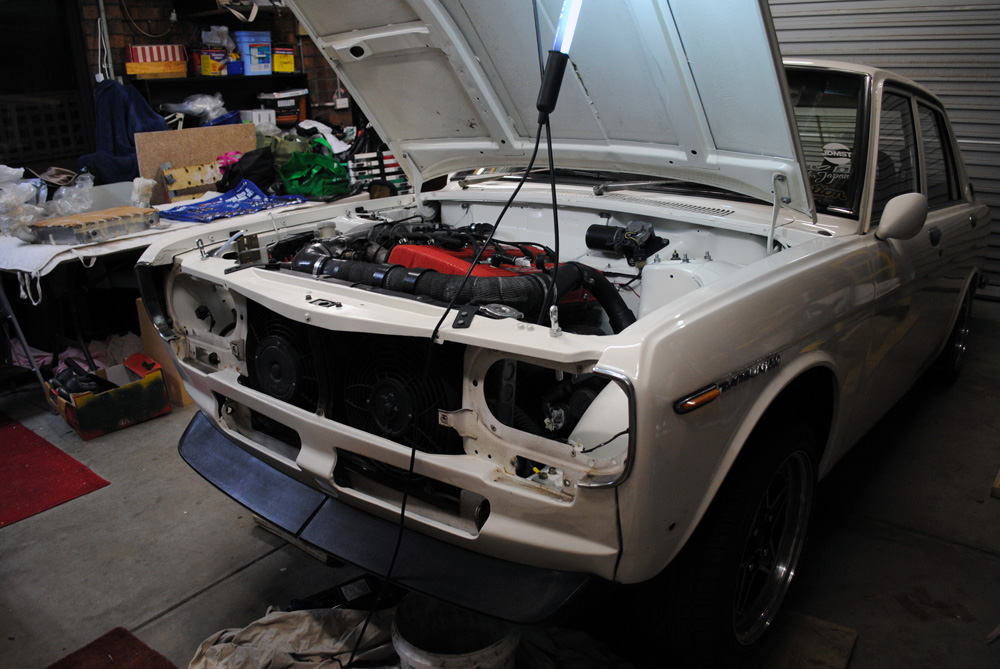
First things first, let’s pull apart a perfectly running and very reliable car. All lights, grilles and bumper were removed.
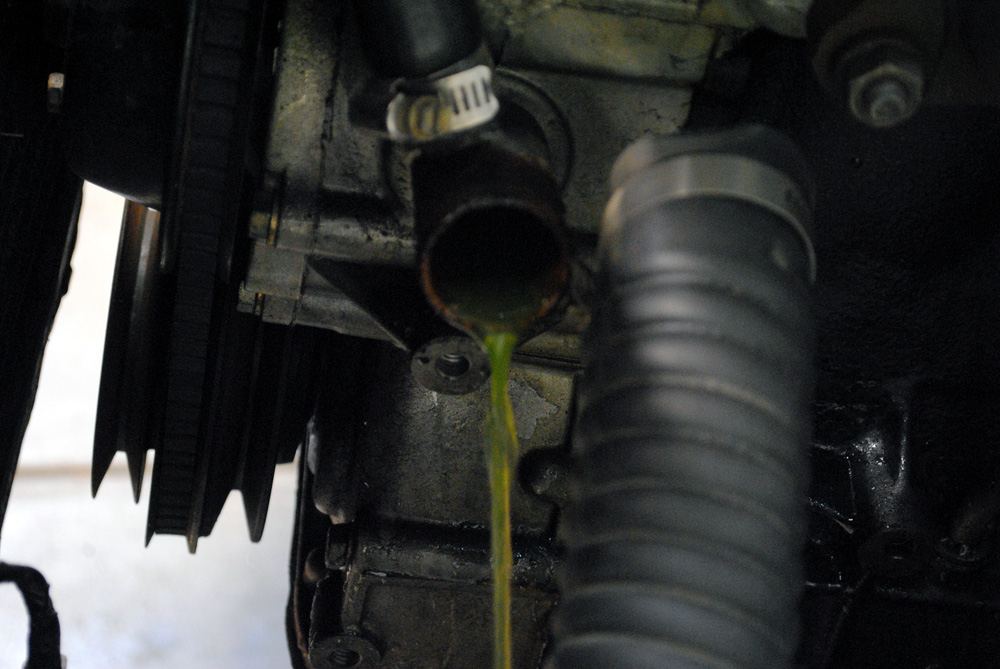
Since the radiator was coming out, the old hoses were removed and all fluid drained.
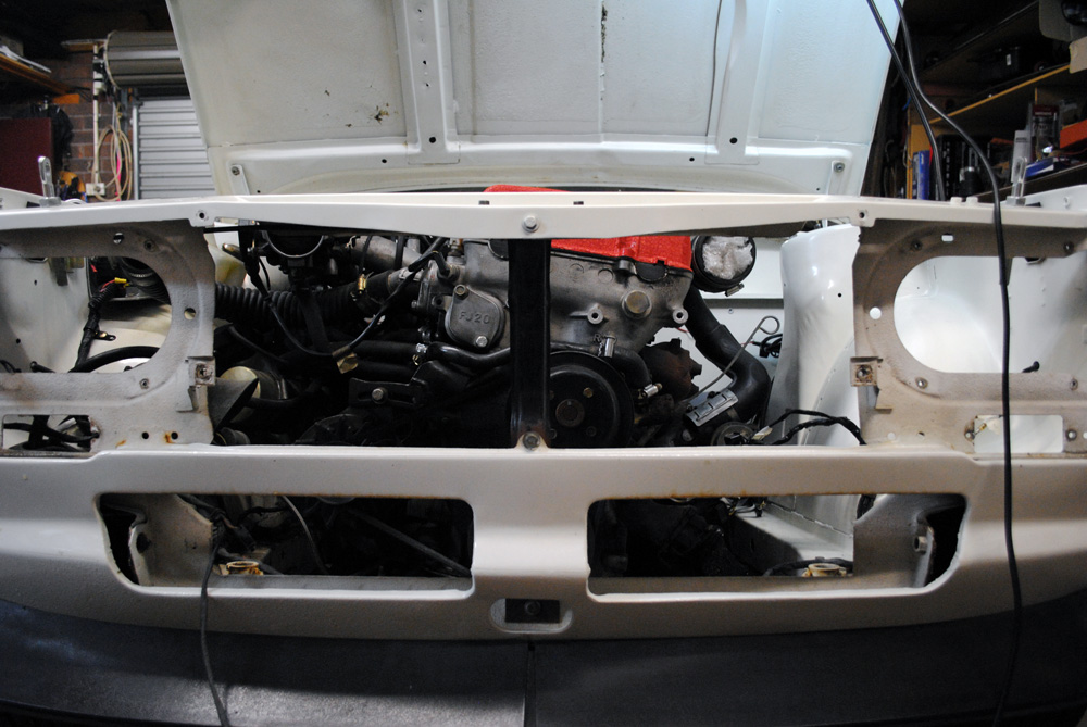
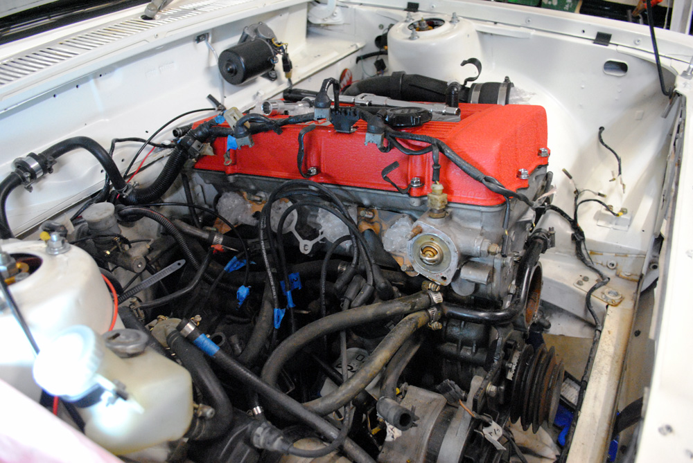
Next the (huge) radiator was removed, giving a full view of the engine from the front end. I needed a smaller radiator as my current one took up all the width between the chassis rails, so I had nowhere to run intercooler piping.
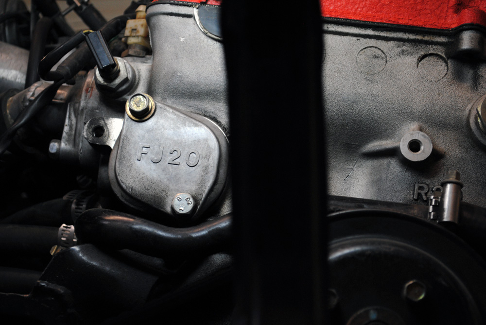
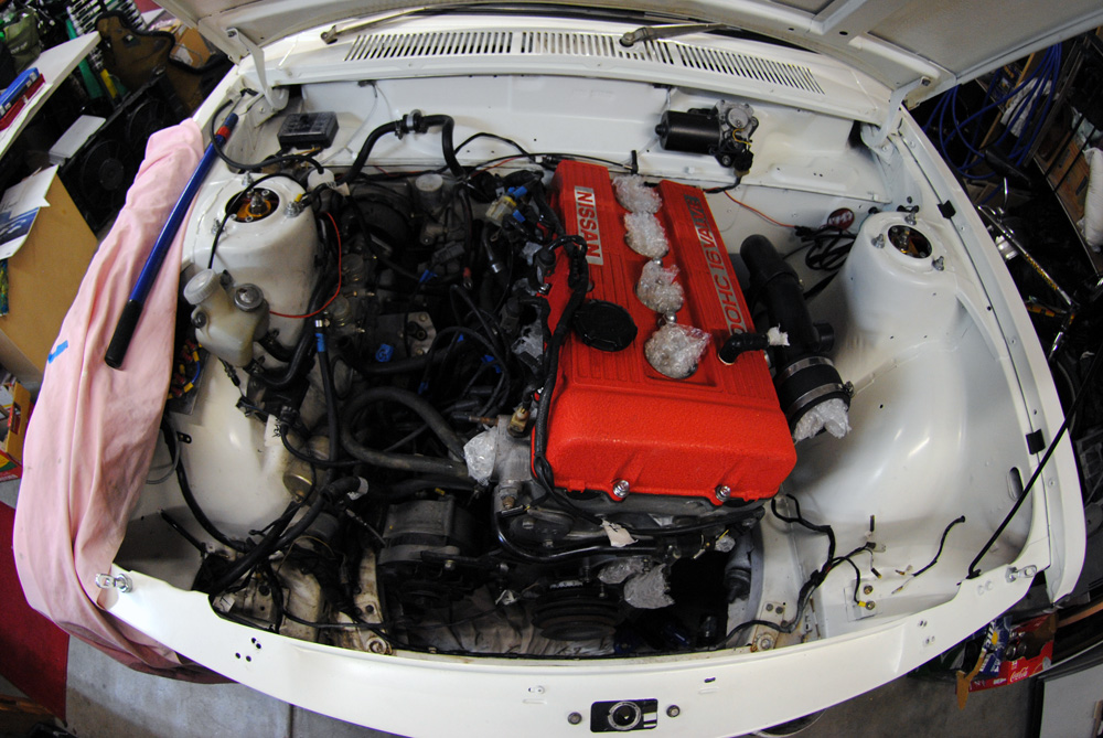
I couldn’t resist an FJ20 glamour shot.
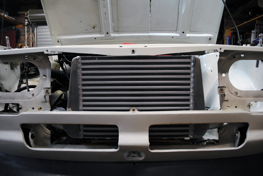
With everything out of the way, I could do a very quick mockup of the intercooler. This is just a generic eBay item that I bought years ago off someone who had some 90 degree bends welded onto the outlets to suit a Datsun 1600. You can see I’ve already started to mark some cuts I need to make on the body of the car near the intercooler outlets.
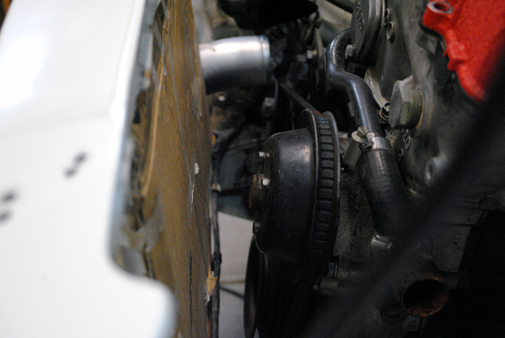
Moving around to the back of the intercooler (with cardboard to protect the fins) you can see why the water pump needs to be removed. In the space between the ‘cooler and engine I still need to fit a radiator and a thermo fan or two. There is just no room to mount all these items and keep the intercooler behind the grille. The only solution is to remove the belt driven pump and go with an electric one mounted off to the side of the engine.
A few quick bolts later…
…and it’s off.
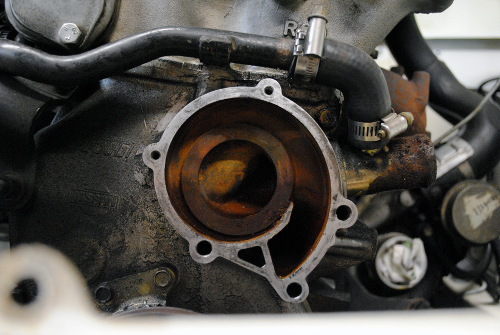
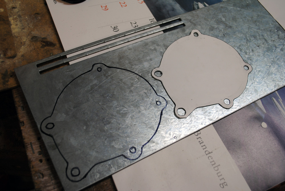
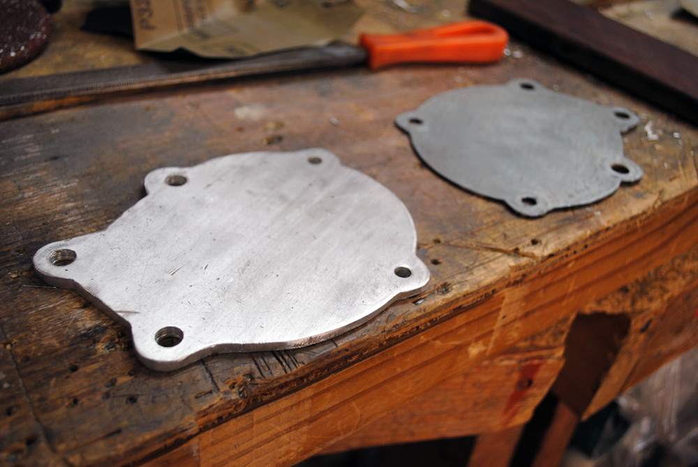
To stop water spewing out everywhere, I needed to block off the gaping hole in the front of my engine. To keep costs down I decided to make my own block-off plate. I first made a paper template, traced it onto some 3mm galvanised plate that I found in the garage, and then cut it out with an angle grinder. After bolting this up to the car I started to have second thoughts about my material choice once I learnt that people were selling block-off plates much thicker than mine.
With that weighing on my conscious I found some 5mm alloy and re-made the block-off plate. Re-making things will be a common theme in this update. I’m not a mechanic, my day job sees me sitting in front of a computer all day, so I’m not afraid to admit I learn as I go and make plenty of mistakes along the way.
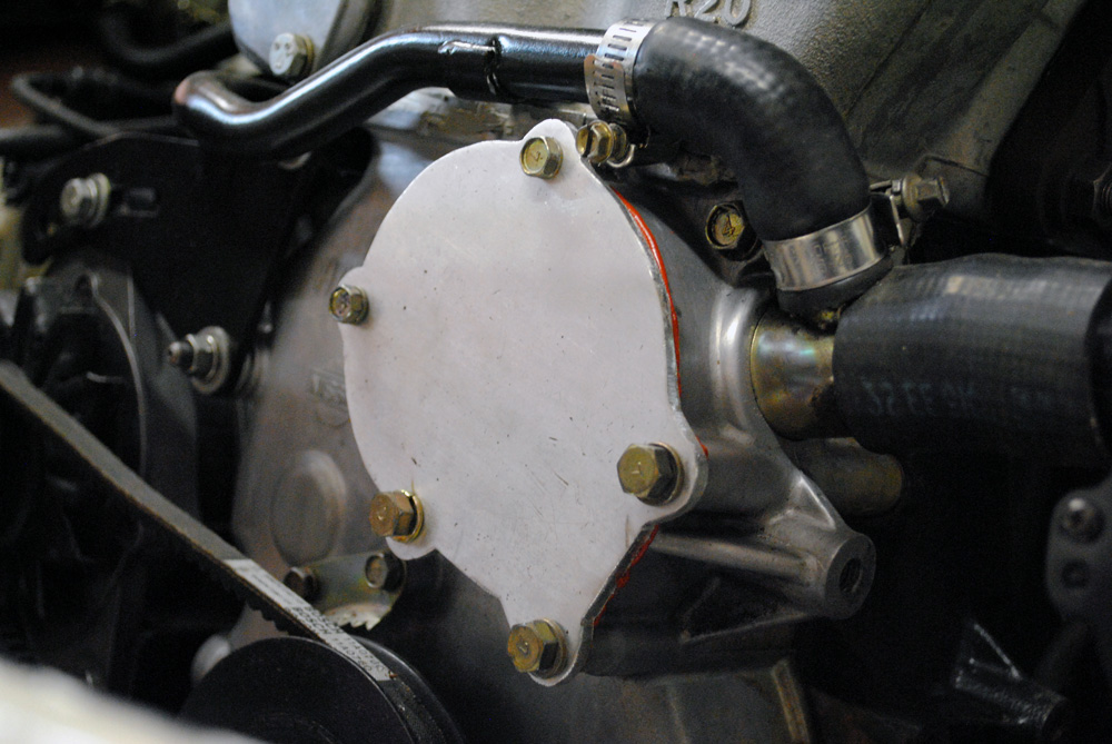
Block-off plate v2.0 bolted and sealed onto the motor. In hindsight I should have used button-head bolts to gain even more room.
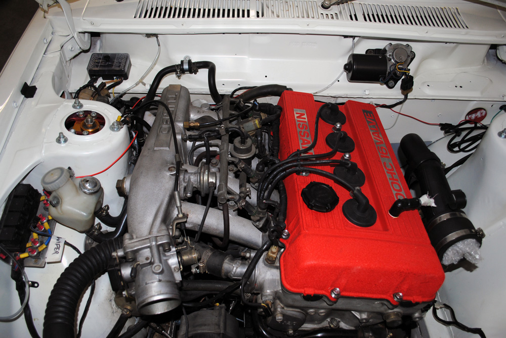
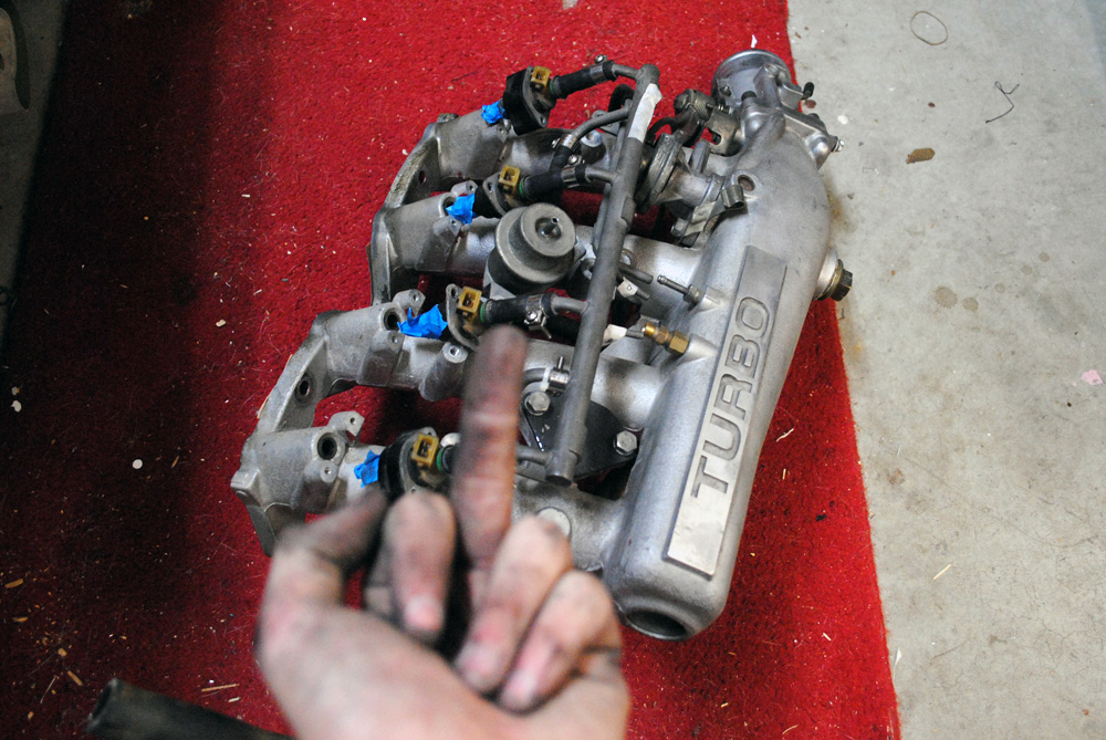
My next job was to remove the intake manifold. The reason the intake manifold needs to be modified is because from the factory, the manifold is cast with the throttle body flange pointing towards the middle of the car (see above). When adding an intercooler, to make routing the piping possible the manifold needs to be cut just behind the T/B flange and then re-welded at a new angle so it either comes out straight or points towards the outside of the car.
Since I was going to the trouble to remove and modify the manifold, I decided to source a smaller one from an S12 Gazelle, compared to my larger DR30 Skyline one. The reason for this was mainly aesthetics and also ease of fitting/removal, as the DR30 one was very large in the small Datsun engine bay.
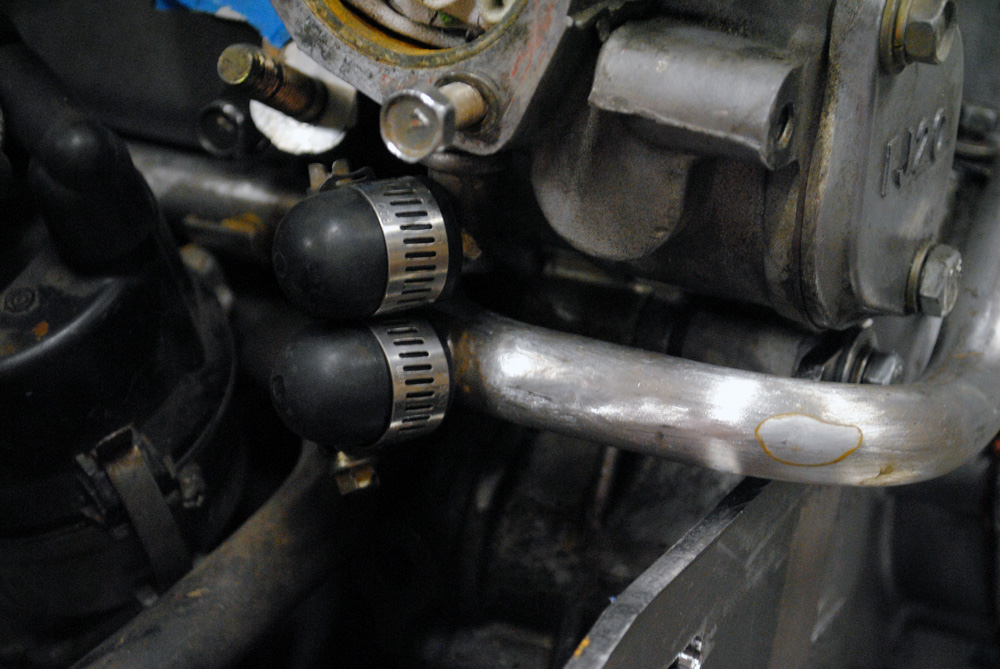
After taking plenty of photos for future reference, removing a lot of stubborn hoses and hard-to-reach bolts, and barely having enough room between the engine and strut tower, I finally removed the manifold. One thing that jumped out immediately was that large looped hose you can see under the thermostat towards the lower center of the image.
A bit of research told me that this was originally meant to be a coolant circuit that ran to a part under the throttle body, to stop it icing up and jamming in colder climate (obviously not Australia!). The previous owner had simply looped it with a long piece of hose, so I sourced some rubber bungs to block them off much more neatly.
There were a few times where I realised just how big of a job I was undertaking (for me, anyway) and this was one of them.
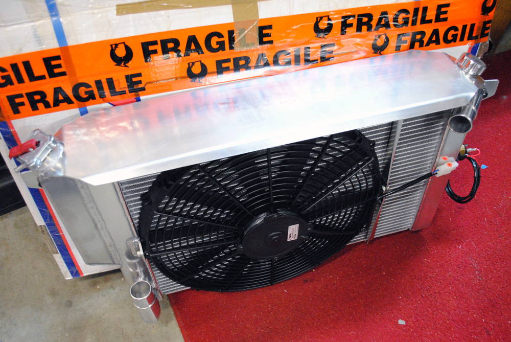
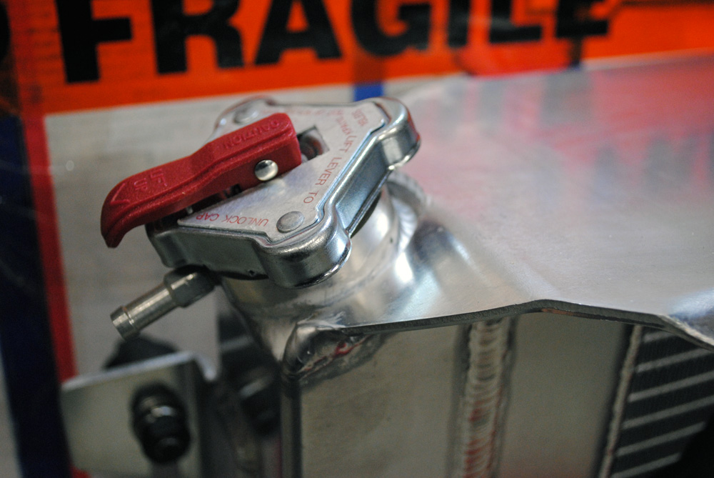
The ‘big ticket’ item of this whole job was definitely my Datsport aluminium radiator. I had originally planned to use an N13 Pulsar radiator (and even purchased one) but even though they are a popular solution for FJ datto’s they are also known to be diffucult when it comes to routing intercooler piping around them. After some careful thinking and piggy-bank smashing, I bit the bullet and ordered a Datsport item, “do it once do it propery “, right?. You can see they are worth the money, with special features like the in-built overflow tank, SPAL thermo fan, and an aluminium mounting plate which locates not only the radiator but also the intercooler.
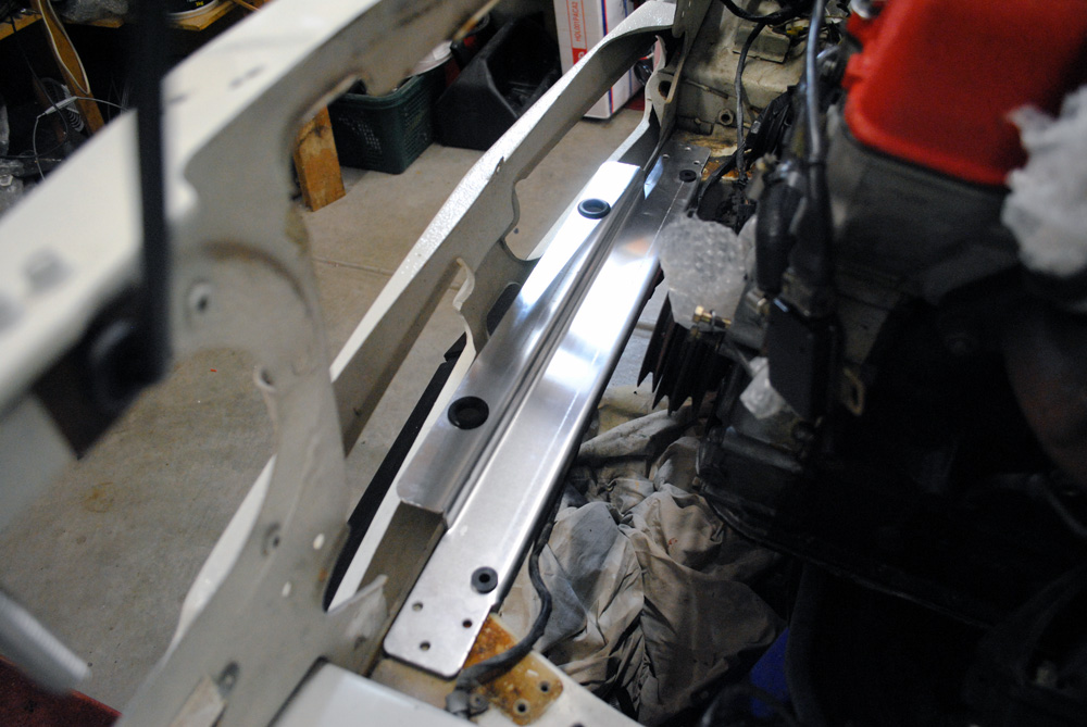
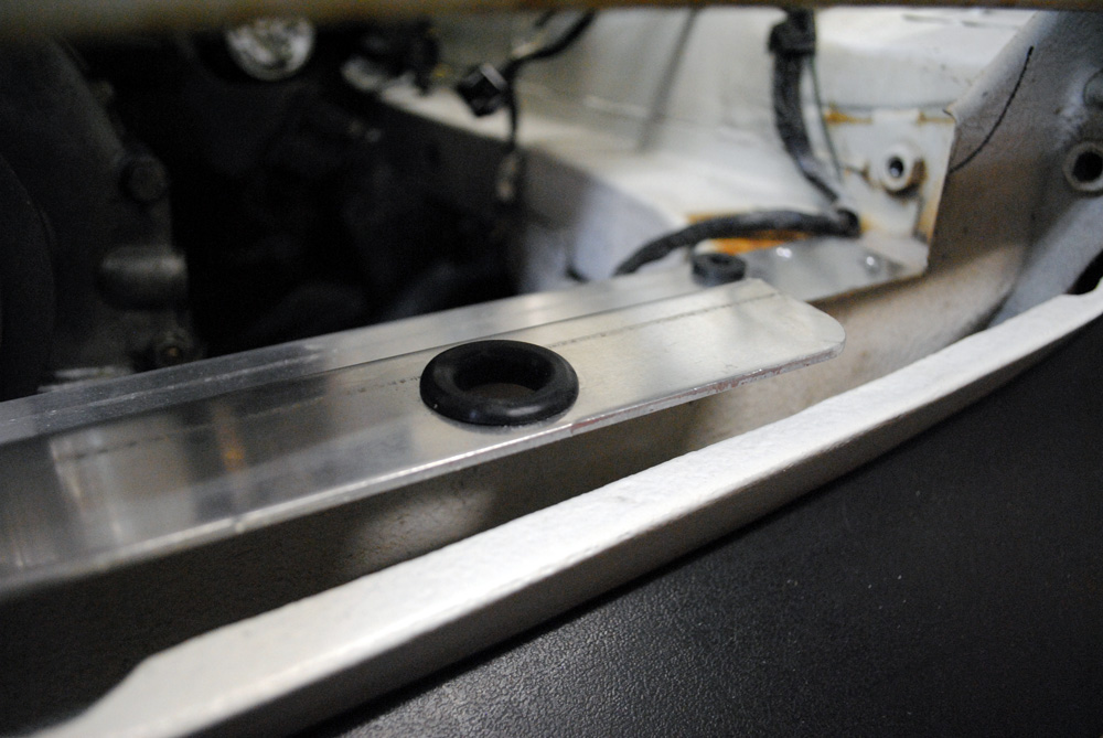
The mounting plate dropped into it’s rough position. The smaller rubber o-rings locate a pair of dowels underneath the radiator, while the larger ones locate the threaded inserts found on most generic intercoolers.
Close-up.
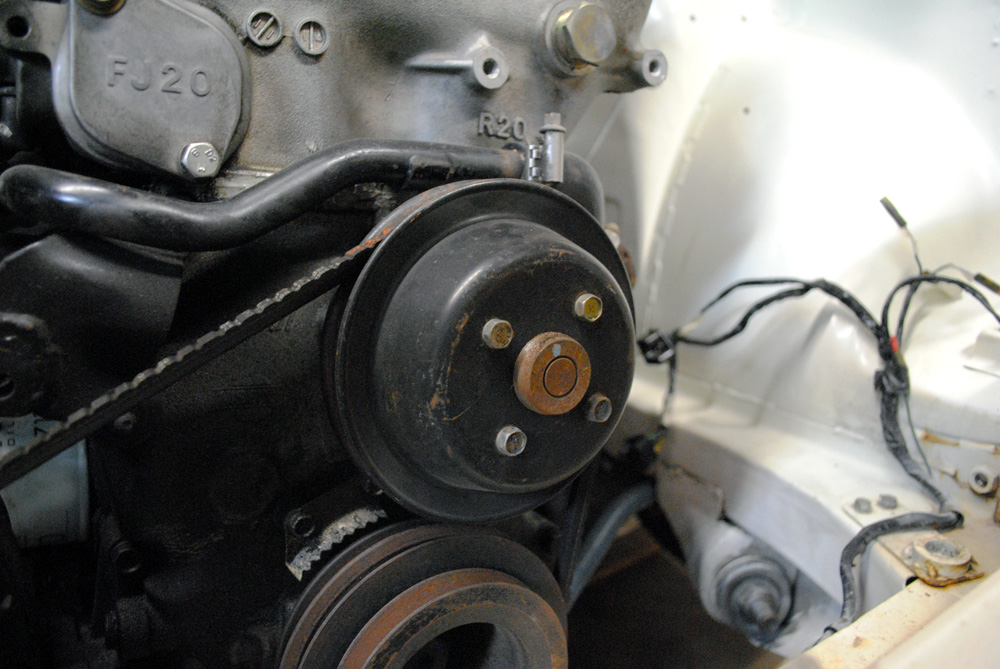
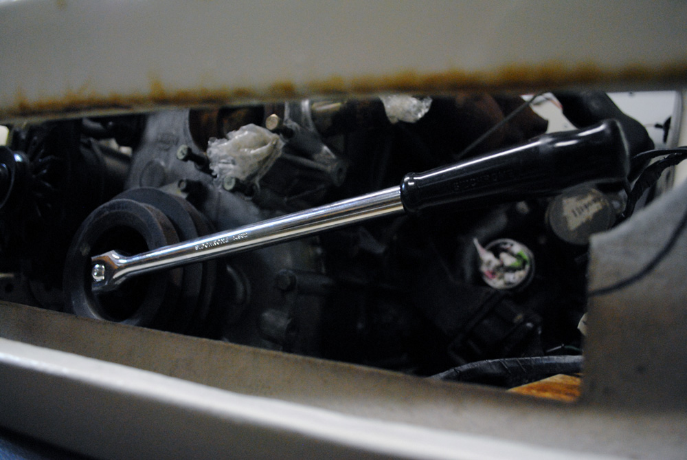
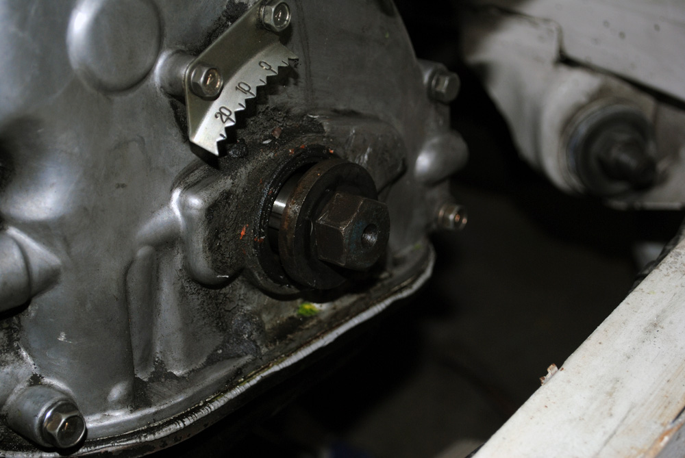
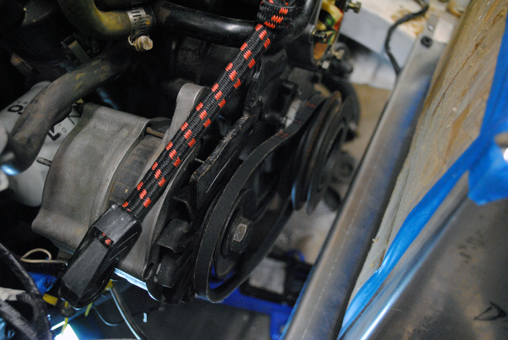
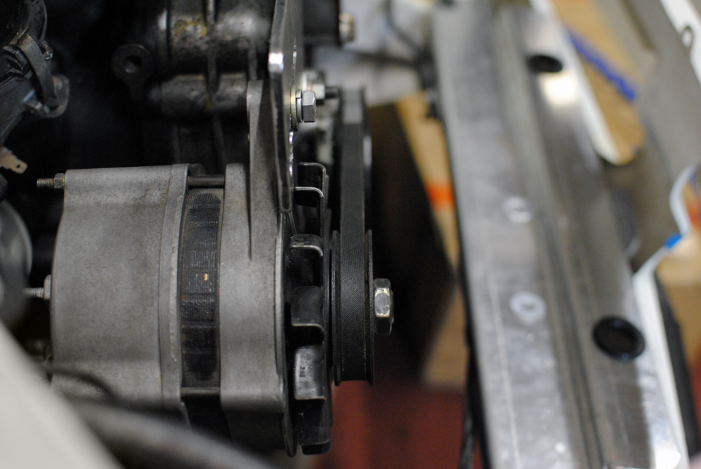
I couldn’t even test fit the radiator, as the thermo fan would be sitting against the crank pulley. My engine only has one belt which goes from the crank pulley, to the (now removed) waterpump, and then to the alternator. The crank pulley has 3 grooves, but I was only using the middle one for my single belt (see this image again for reference), so the front groove was doing nothing and could be sacrificed. I failed to remove the single nut which holds the crank pulley using my air-compressed impact gun, so I asked around and was told about the ‘starter trick’. This involved attaching a socket and breaker bar onto the nut, with the breaker bar handle sitting a few inches above the chassis rail, and then shitting myself while I cranked the engine over with the fuel relay disconnected. This makes the crank rotate and forces the breaker bar to hit the chassis rail where it cannot go any further, bottoming it out and transferring the force onto the nut which then easily un-does itself.
I was surprised at how well it worked. I placed a stack of cardboard on the chassis rail so the breaker bar wouldn’t damage it when it made contact.
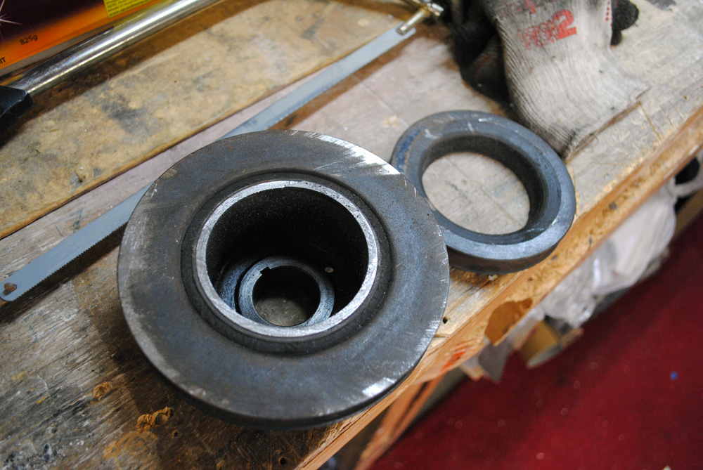
With the pulley removed I was able to cut off the un-needed groove with a hacksaw, as there was a gap between itself and the next groove, so it was easy. After mockup stage I had planned to take the pulley to be professionally re-balanced, but my plans changed. The two remaining grooves are a single piece joined together, and adhered to the center key with a rubber isolator.
I don’t have a picture of how the radiator sat with the grove cut off the pulley, but I can tell you it still interfered.
My next call to action was to shave off some of the material on the plastic shroud around the thermo fan, but even this didn’t give me the clearance I needed. I think this is due to my engine mounts and how they position the motor in the bay, from what I can tell my engine sits a bit further forward than other FJ 1600′s, as some other people run this radiator and don’t have the clearance issues I have. After yet more research I decided my only choice was to mount the alternator 20mm rearwards so the belt would use the groove on the crank pulley which is closest to the engine, and then have the other groove machined off.
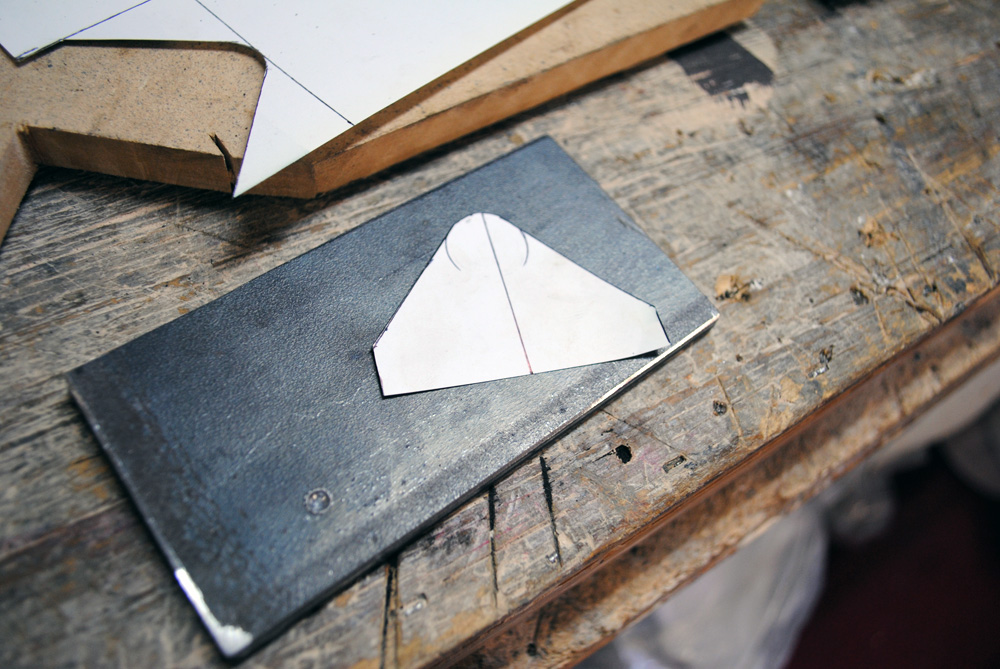
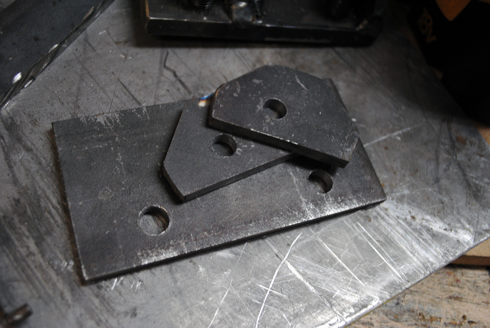
After removing the alternator I inspected the standard mount and started researching how to make a new one. In the end I decided to make it out of 3 pieces of flat plate.
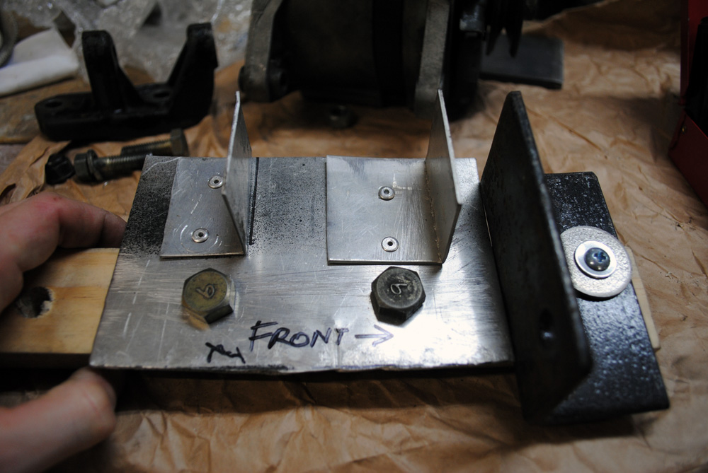
First, I made a very crude jig, and I use the term “jig” loosely!
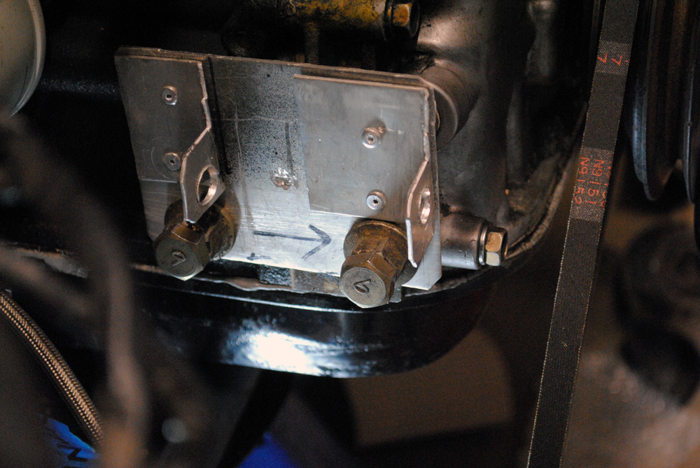
Next, I made a very quick mock-up mount out of thin aluminium, with the forward mounting tab located 20mm further back than the original.
Bolted to the engine…
…and then the alternator bolted up to quickly check I was on the right track. So far so good.
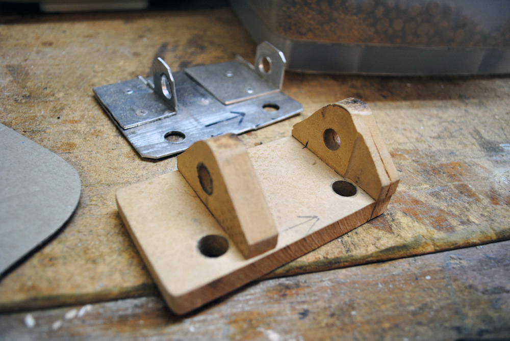
To make extra-sure that I wasn’t wasting my time, I made a second mockup out of MDF to ensure that the design would work with a thicker material, and it did, so next it was onto the final metal version.
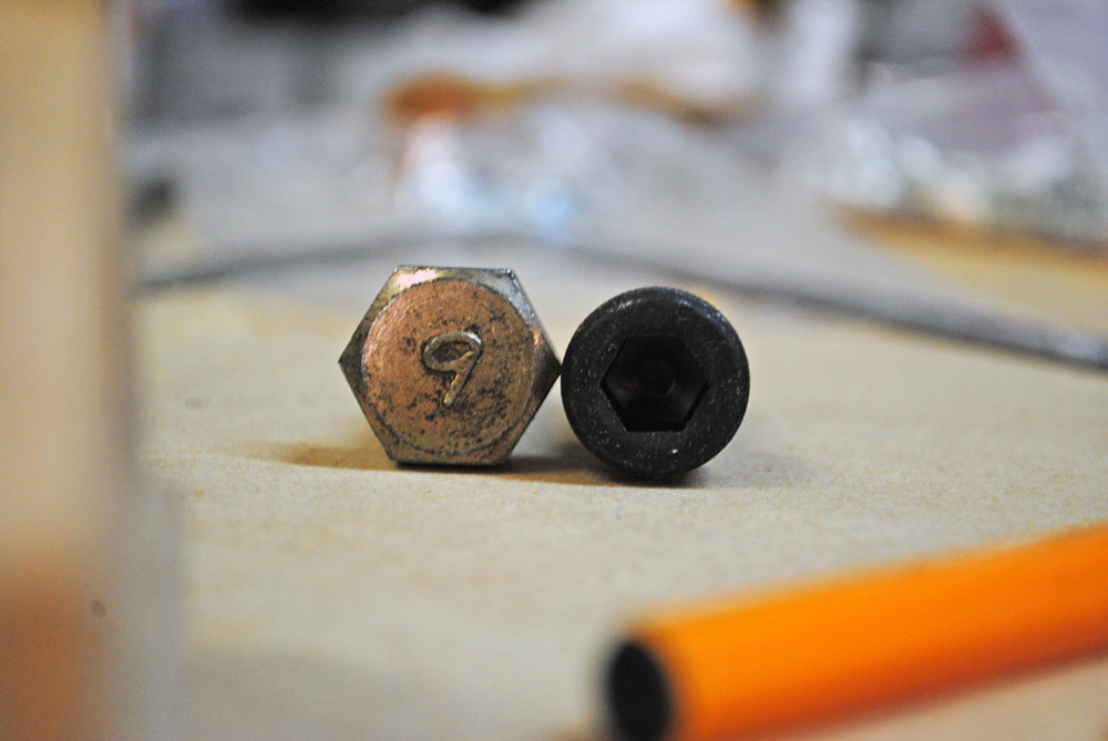
Since the bolt holes had to be fairly close to the mounting tabs, I bought a couple of allen-head bolts to save some room.
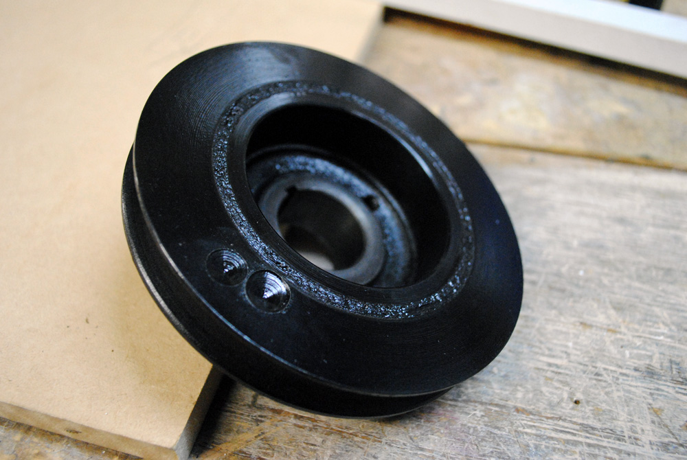
While all this was happening, I sent my crank pulley away to be machined down to one single groove and then re-balanced. You can see the metal that was removed during the balancing process.
When it came time to make the metal alternator mount, I decided I’d had enough of relying on other people to weld things for me and did something I’ve wanted to do for a long time…
I bought myself a mig welder, gloves, a helmet, picked up some scrap metal and signed myself up for a gas account. What followed was lots of Youtube tutorials and lots of practice. After I started getting confident I decided I was ready to attack the alternator mount.
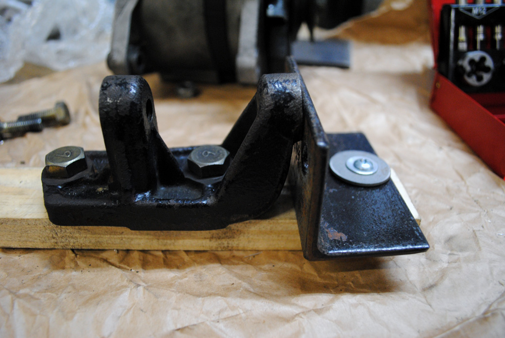
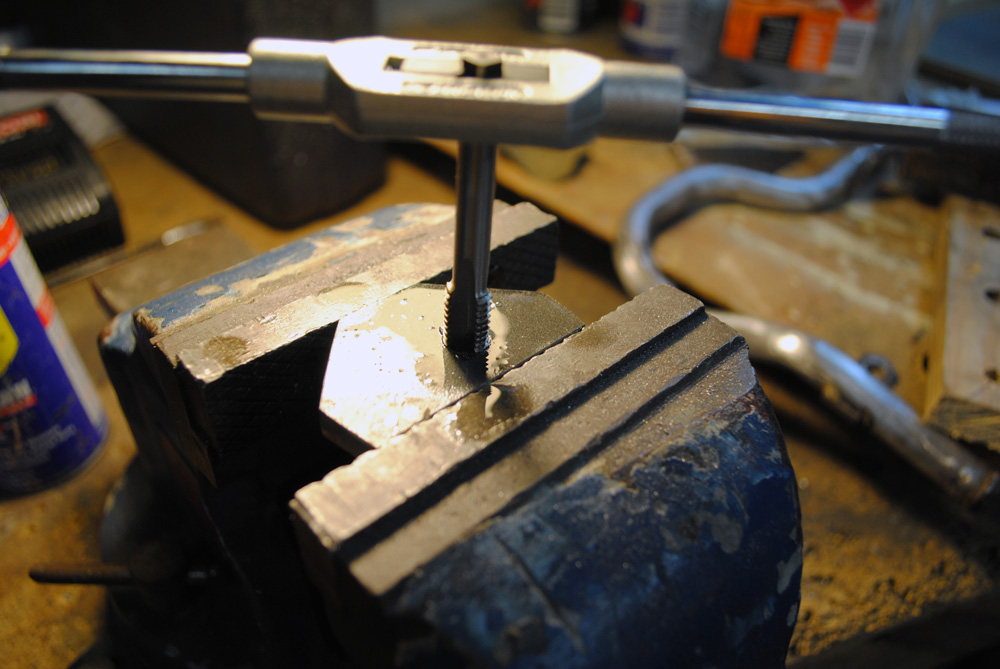
Thanks to Tony from The Motor Report for kindly lending me his tap and die set for a very long time. It came in handy on a few occasions.
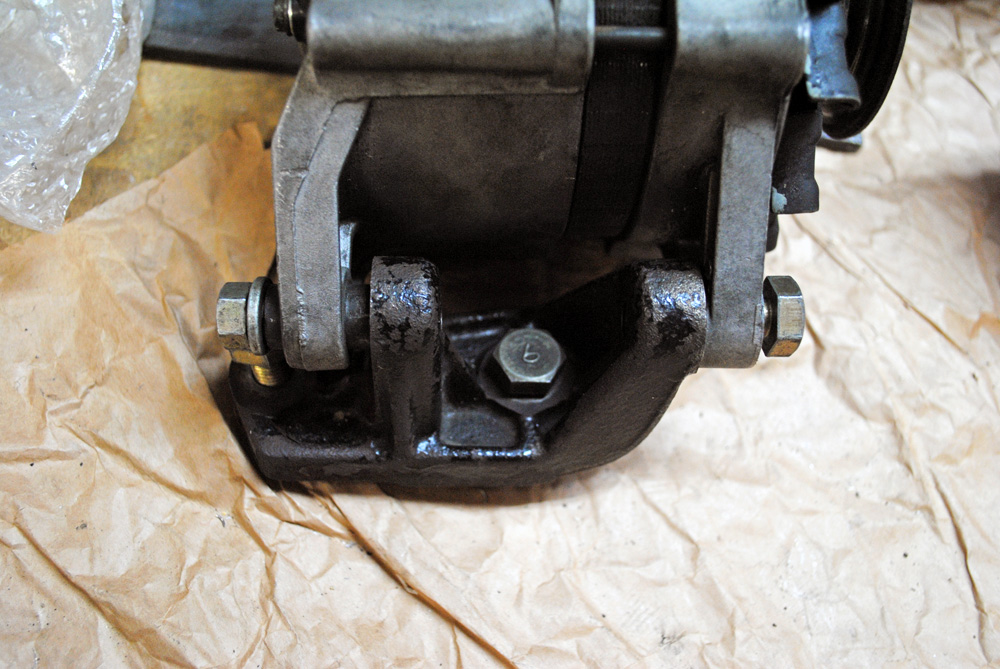
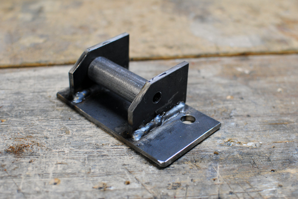
The final mount. I added in a tube between the tabs for extra strength (not yet welded in the above photo). Naturally all of my practice welds were way better than when I tried to replicate them on the final piece, so annoying!
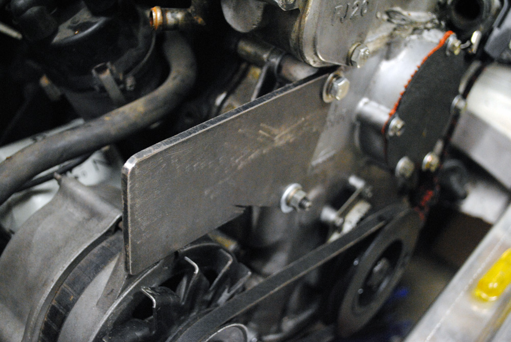
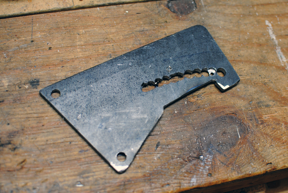
Another item I had to make for the alternator was the upper adjusting bracket. Again, I started with some 5mm scrap metal, spaced it off the engine until it was in the right position. (v1 waterpump blockoff plate pictured)
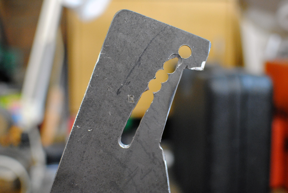
After working out the arc of the alternator, I started drilling holes…
…and then started joining them up with a die-grinder I loaned from my mate Gaz (thanks mate!)
Another test fit.
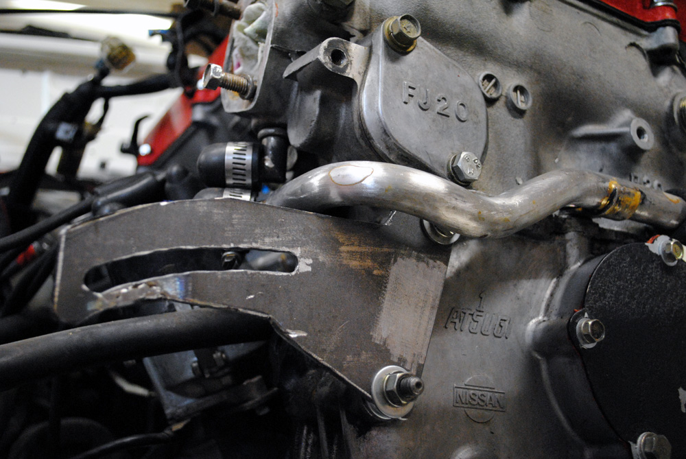
I had to clearance the top of the plate for the water pipe to fit above it.
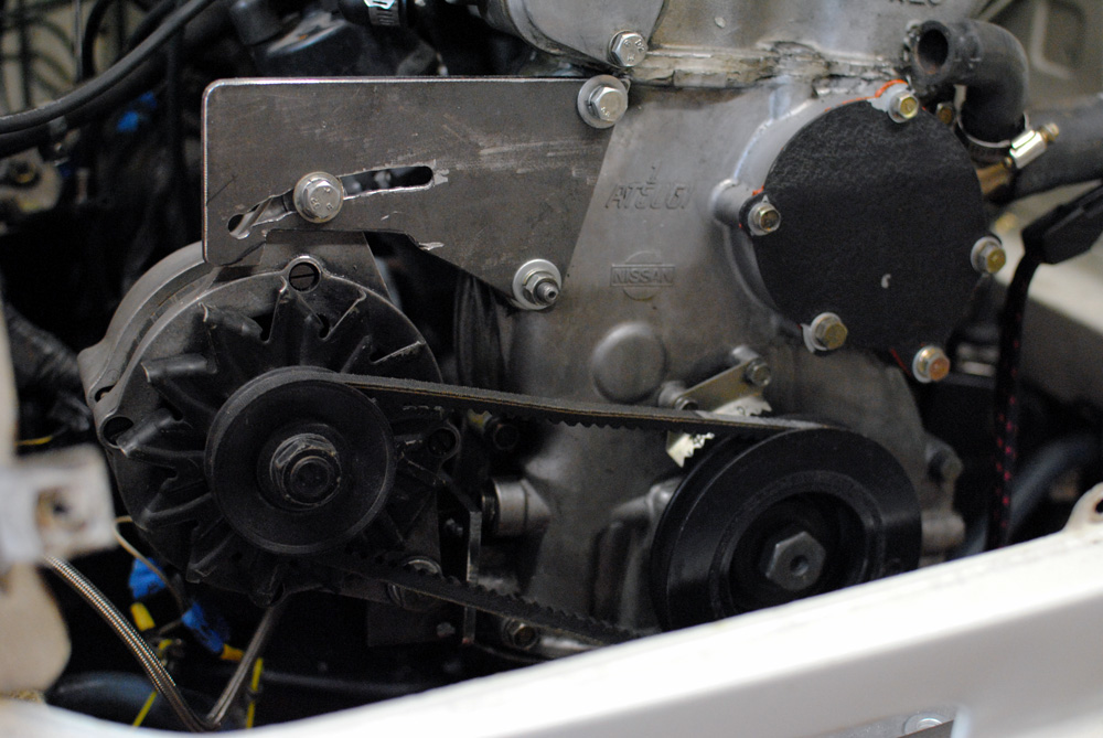
With both mounts fitted up I was very pleased to see that everything lined up well and the alternator was able to be adjusted easily. The true test would be when the engine fired up for the first time.
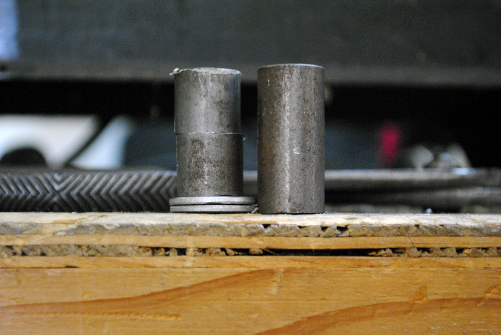
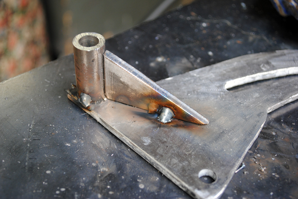
Up until this point I was using various pieces of tubing and washers to space the upper bracket, so once the design was finalised I cut down one piece of pipe to the correct length.
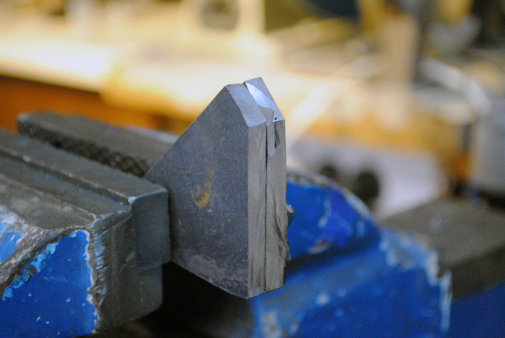
I also added a triangular gusset for some extra strength to try to reduce any flexing, since it’s essentially a flat plate.
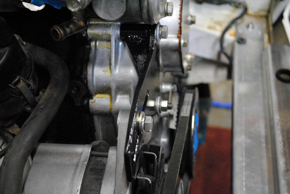
Welded, painted, and fitted for the final time.
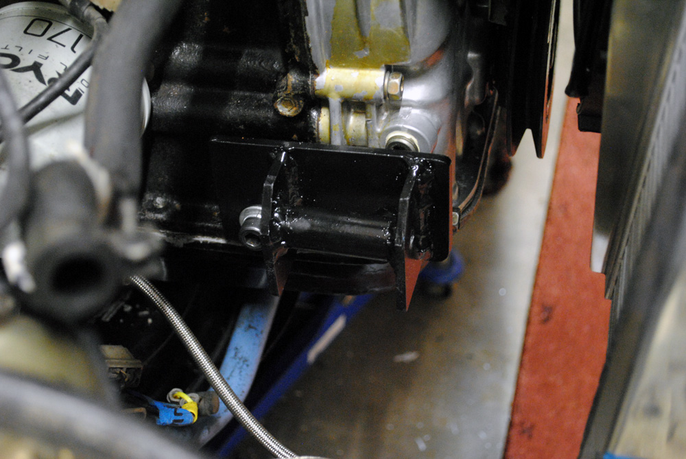
Mounting bracket painted and fitted. You can also see the amount of clearance I gained between the crank pulley and the radiator/thermo fan.
With the alternator relocation out of the way I was now back to where I started; fitting the intercooler, radiator, and modifying the intake manifold! It was a huge setback for me and it took a lot of time to complete, sometimes feeling like I was going nowhere, but once it was out of the way I concentrated on moving forward and the real progress started to happen.
To be continued…
Original: Build Threads

